为什么从QGraphicsScene渲染的PNG图像出现错误偏移?
我有一个程序,它可以把一个 QGraphicsScene 的内容画成 PNG 图片。不过我发现,在某些情况下,生成的 PNG 图片不太对劲。具体来说,生成的图片好像有点“偏移”,也就是说,QGraphicsScene 的左上角并不在 PNG 图片的 (0,0) 这个位置。
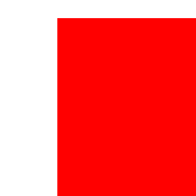
下面的代码展示了这个问题。createImage 函数会创建一个指定宽度和高度的 QGraphicsScene,然后在 (0, 0) 的位置画一个和场景一样大小的红色矩形,接着把这个场景渲染成图片并保存到文件里。我认为这个函数无论给多大的宽度和高度,都应该输出一张纯红色的图片。但是,这里有一张输出图片的例子,说明情况并不是这样。
testImage 函数(依赖于 PIL)会读取这张图片,并检查最右边的那一列和最下面的那一行。如果图片出现了错误的“偏移”,那么在最下面的那一行或最右边的那一列会找到一个白色的像素。如果图片生成得正确,最下面的那一行和最右边的那一列应该只有红色像素。(PIL 在这里并不是问题的根源,我只是用它来自动化测试输出的图片。)
#!/usr/bin/env python

import sys
import Image        # Requires PIL
from PyQt4.QtCore import Qt, QRect, QRectF
from PyQt4.QtGui import QPen, QBrush, QGraphicsScene, QGraphicsView, QGraphicsRectItem, QPixmap, QPainter, QApplication

whitebrush = QBrush(Qt.white)
redbrush = QBrush(Qt.red)

RED = (255, 0, 0)

def createImage(width, height):
    scene = QGraphicsScene(0, 0, width, height)
    scene.setBackgroundBrush(whitebrush)

    rectangle = QGraphicsRectItem(0, 0, width, height)
    rectangle.setPen(QPen(Qt.NoPen))
    rectangle.setBrush(redbrush)
    rectangle.show()
    scene.addItem(rectangle)

    view = QGraphicsView()
    view.setScene(scene)

    outputimg = QPixmap(width, height)
    painter = QPainter(outputimg)
    targetrect = QRectF(0, 0, width, height)
    sourcerect = QRect(0, 0, width, height)
    view.render(painter, targetrect, sourcerect)
    outputimg.save("output.png", "PNG")

    painter.end()

def testImage(width, height):
    image = Image.open("output.png")
    ok = True

    for x in range(width):
        if image.getpixel((x, height - 1)) == RED:
            if x > 0:
                print "First red pixel on bottom row is at x = %d" % x
                ok = False

            break
    else:
        print "No red pixels found on bottom row"
        ok = False

    for y in range(height):
        if image.getpixel((width - 1, y)) == RED:
            if y > 0:
                print "First red pixel in rightmost column is at y = %d" % y
                ok = False

            break
    else:
        print "No red pixels found in rightmost column"
        ok = False

    if ok:
        print "Image OK"

def doTest(width, height):
    createImage(width, height)
    testImage(width, height)

if __name__ == "__main__":
    app = QApplication(sys.argv)
    doTest(int(sys.argv[1]), int(sys.argv[2]))
这里有几个示例运行的结果:
$ ./qgraphicssceneimagetest.py 200 200
No red pixels found on bottom row
No red pixels found in rightmost column
在这个情况下,“偏移”的效果非常明显,整个输出图片都是白色的。
$ ./qgraphicssceneimagetest.py 400 400
First red pixel on bottom row is at x = 117
First red pixel in rightmost column is at y = 37
这是生成我上面提到的示例图片的情况。
$ ./qgraphicssceneimagetest.py 500 500
First red pixel on bottom row is at x = 55
此时,图片在垂直方向上偏移是正确的,但红色矩形仍然向右偏移了 55 像素。
$ ./qgraphicssceneimagetest.py 600 600
First red pixel on bottom row is at x = 5
现在几乎正确了……
$ ./qgraphicssceneimagetest.py 700 700
Image OK
所以看起来,如果图片足够大,代码是可以正确生成输出图片的。
实际上,我有一个解决这个问题的办法。如果我把 createImage 函数中的一行代码替换成
sourcerect = QRect(0, 0, width, height)
就可以正确生成图片。
    xoff = 0
    yoff = 0

    if width <= 634 and height <= 474:
        xoff = (634 - width) // 2
        yoff = (474 - height) // 2
    elif width < 610:
        xoff = (610 - width) // 2
    elif height < 450:
        yoff = (450 - height) // 2

    sourcerect = QRect(xoff, yoff, width, height)
我不知道这段代码中的“魔法”数字有什么特别的意义。不过,我用这个解决办法做了很多测试,确认它们都生成了正确的纯红色图片。
有这个解决办法当然不错,但我想了解为什么这些图片会生成不正确。是不是我漏掉了什么或者忘记做了什么?
1 个回答
发生的情况是,视图会自动计算一个矩形区域来显示场景,然后根据添加的图形项目进行居中。根据这些项目的大小,有时候这会导致边缘留出空白区域。
解决办法是明确设置一个矩形区域来定义场景:
view = QGraphicsView()
view.setScene(scene)
view.setSceneRect(QRectF(view.viewport().rect()))